Vapor Compression Refrigeration Cycle Pv Diagram
Vapor Compression Refrigeration

Vapor Compression Refrigeration Wikipedia
Design Of Vapor Compression Refrigeration Cycles

T S Diagram Of The Vapour Compression Refrigeration Cycle Considered In Download Scientific Diagram
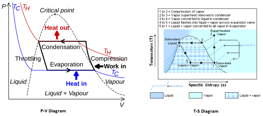
Diagram Vapourpression Refrigeration Cycle T S Diagram Full Version Hd Quality S Diagram Obadiagram Le Saint Germain Fr
Explain Vapour Compression Refrigeration Cycle On T S And P H Charts Topicwise Paper Solutions For Msbte

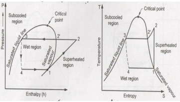
T s diagram for a vapour compression refrigeration cycle when the refrigerant leaves the evaporator as a saturated vapour b superheated vapour.
Vapor compression refrigeration cycle pv diagram. A cooler where we reject the heat a throttle a heater where we absorb the. 1 in practice the refrigerant enters the compressor at state 1 slightly superheated vapor instead of. The 2 refrigeration cycles as explained below primarily differ in this process of vapor recovery. The vapor compression refrigeration cycle.
Isentropic compression for state 1. It is also used in domestic and commercial refrigerators large scale warehouses for chilled or frozen storage of foods and meats. The simplest gas refrigeration cycle is the reversed brayton cycle. In this refrigeration cycle system the refrigerant vapor from the evaporator is sucked in by a compressor which then compresses the vapor to a higher pressure.
A refrigerant design problem for a vapor compression refrigeration cycle was presented previously gani et al 2017. A low pressure low temperature liquid is converted to vapor in the evaporator thus absorbing heat from the refrigerated space and keeping that space cool. Vapor compression cycle thermodynamic cycle of heat pumps. The design is to be based upon the ideal vapor compression refrigeration cycle with four components.
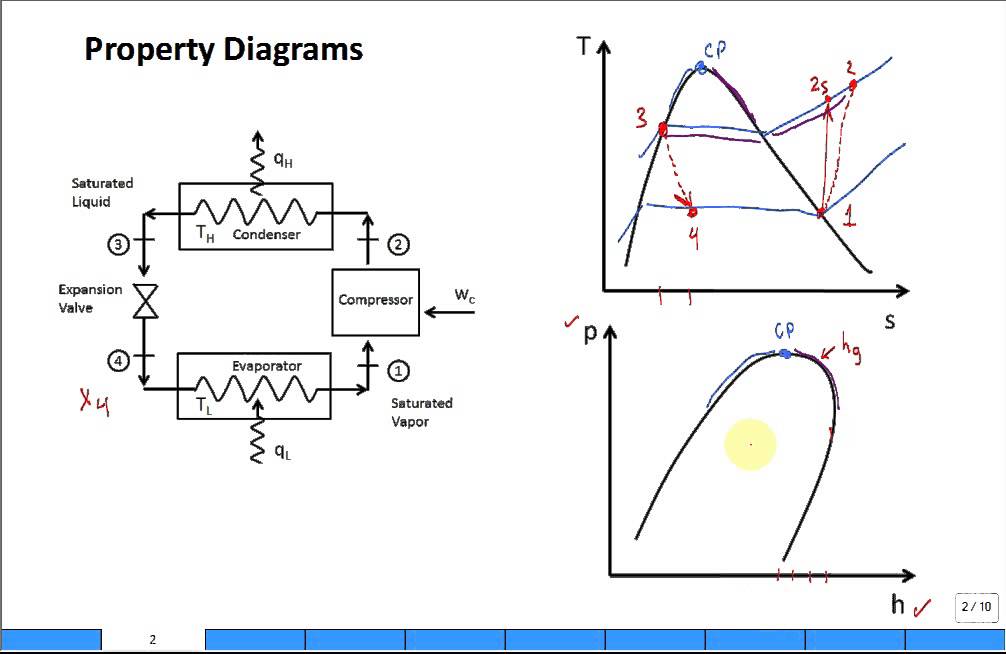
In this paper the case study was extended to include an expanded search space inclusion of utility streams and practical design criteria. The vapor compression uses a circulating liquid refrigerant as the medium usually r134a which absorbs and removes heat from the space to be cooled and subsequently rejects that heat elsewhere the figure depicts a typical single stage vapor compression system the typical vapor compression system consist of four components. Dec 4 2019 pv diagram of the vapor compression refrigeration cycle. Kalakul et al 2016.
Actual vapor compression refrigeration cycle fig. We want to design a vapor compression refrigeration cycle to absorb heat from a cool environment and reject it to a warm environment. Vapour compression refrigeration or vapor compression refrigeration system vcrs in which the refrigerant undergoes phase changes is one of the many refrigeration cycles and is the most widely used method for air conditioning of buildings and automobiles. Most of the differences between the ideal and the actual cycles are because of the irreversibilities in various components which are.
2a compressor vapor compression cycle. The vapor compression refrigeration cycle is nearly 200 years old but it does not seem ready to leave the scene any time soon. Gas refrigeration cycle a schematic diagram b t s diagram. T s diagram for actual vapor compression cycle.
The diagram at the left shows the components of a vapor compression refrigeration cycle. Hence the system is called a vapor compression.
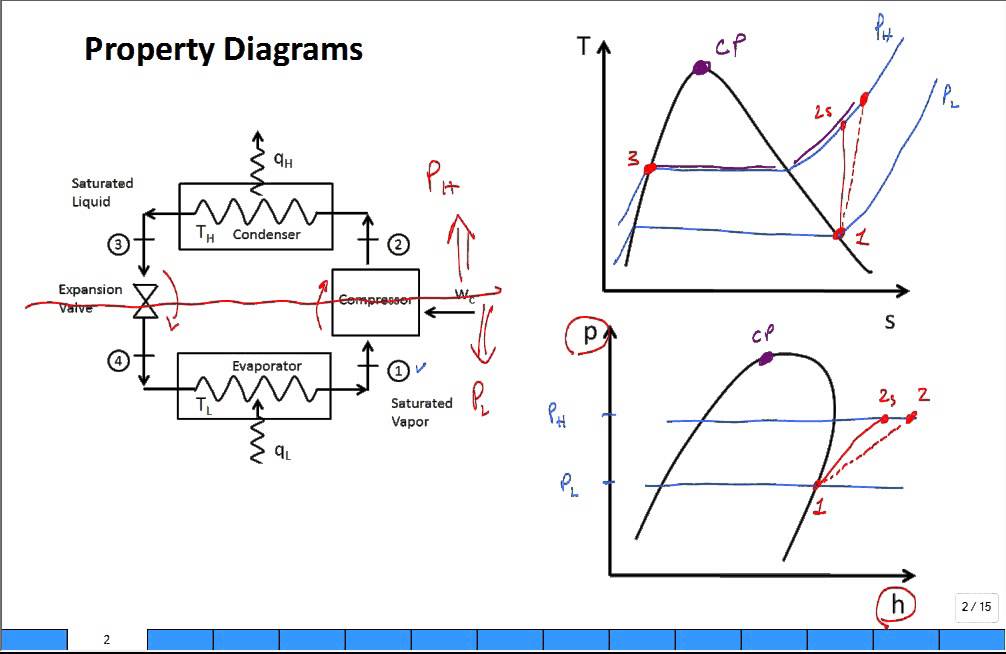
Property Diagrams Ts And Ph For Refrigeration 2 Youtube

File Refrigeration Pv Diagram Svg Wikimedia Commons
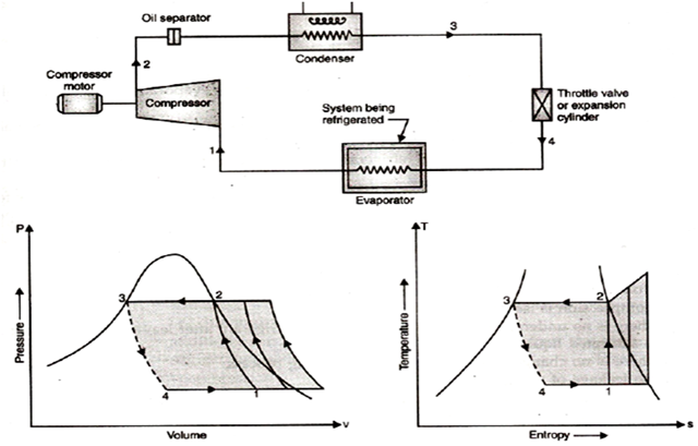
Vapour Compression Refrigeration Cycle Engineering Tutorials

P H Diagram Of The Vapour Compression Refrigeration Cycle Considered In Download Scientific Diagram

Vapor Compression Refrigeration Cycle Interactive Simulation Youtube
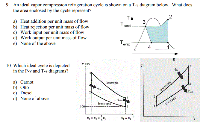
Solved 9 An Ideal Vapor Compression Refrigeration Cycle Chegg Com
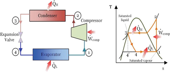
Energy And Exergy Analysis Of Refrigeration Systems Intechopen
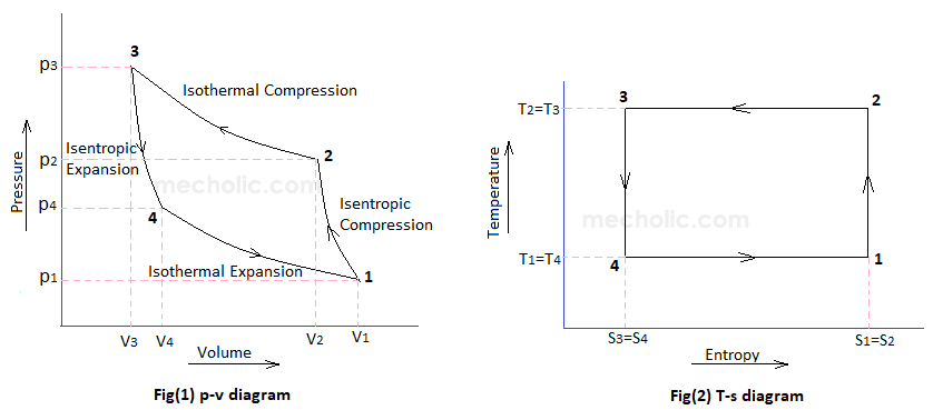
Cop Of Air Refrigerator Working On Reversed Carnot Cycle With Pv And Ts Diagram Mecholic

P H Diagram Of Vapor Compression Refrigeration Cycle Generally The Download Scientific Diagram

Refrigeration Cycle A Helpful Illustrated Guide Refconhvac Com

Ch10 Lesson B Page 3 Cop Ideal Vapor Compression Refrigeration Cycles

Vapour Compression Refrigeration Cycle Components Working Process Applications Pdf
Property Diagrams Ts And Ph For Refrigeration Youtube