Vapor Compression Refrigeration Cycle Ph Diagram

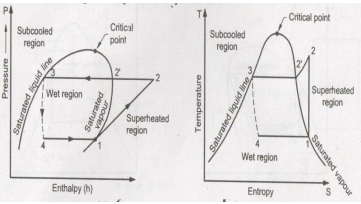
T s and p h diagrams for an ideal vapor compression refrigeration cycle.
Vapor compression refrigeration cycle ph diagram. Such a superheating is called useless superheating as it does not increase refrigeration effect. 4 3 performance of refrigeration system. The performance of refrigeration plant is expressed as co efficient of performance cop which is defined as the ratio of refrigerating effect produced to the work of compression. The layout shown below is a clickable image.
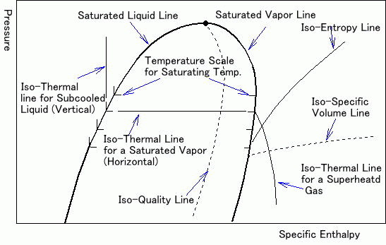
The area to the left of the thumbprint are properties of liquid refrigerant and to the right. The theoretical vapour. Actual vapour compression refrigeration cycle. In this cycle the refrigerant is sealed condition in an airtight mechanism is compressed in a compressor which permits the transfer of heat energy.
The points which are required for engineering calculation are from h 1 to h 6 as shown in the figure 1 6. Basic refrigeration cycle centrifugal compressors leak testing service set ups tips using pressure enthalpy diagrams. The refrigerant absorbs heat from one place and releases it to another place. A reversible adiabatic isentropic compression of the refrigerant.
Bahrami ensc 461 s 11 refrigeration cycle 3 fig. Vapour compression cycle generally known as vcc is a refrigeration cycle. 4 1 constant pressure heat absorption. H 1 to h.
The saturated vapor at state 1 is superheated to state 2. Vapor compression refrigeration cycle t s diagram below is a possible cyclepad design of a refrigeration cycle. 2 3 constant pressure cooling heat rejection. 1 24 2018 2 comments.
Fig 1 a and b shows the vcrs cycle without and with subcooling on p h and t s coordinates. Compression and the p h diagram. 3 4 isenthalpic expansion through expansion valve. While some people have viewed this method as environmentally harmful and inefficient the cycle is still applicable in the industrial sphere.
Vapour compression refrigeration cycle p h diagram explain the vapor compression cycle on the t s and p h diagrams for the heated steam at the end of the compression the p h and t s vapor compression cycle for a simple steam compression cooling cycle is shown in the pattern for the steam entering the compressor is in a dry state of saturating dry. Mixtures of liquid and vapor. 1 2 isentropic compression in compressor. Figure 1 5 refrigeration cycle on the p h diagram take the structure image of this refrigeration cycle from figure 1 5 it becomes the p h diagram for engineering calculation as shown in figure 1 6.
1 a p h diagram with and without subccoling b t s diagram with and without subcooling. Wc h2 h1. 4 1 actual vapor compression refrigeration cycle on p h diagram.


