Actual Vapor Compression Refrigeration Cycle T S Diagram

T S Diagram Of The Vapour Compression Refrigeration Cycle Considered In Download Scientific Diagram

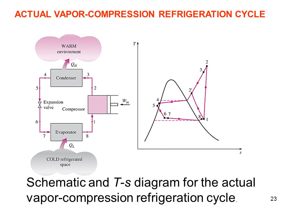
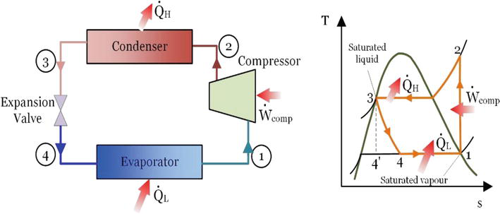
Schmatic And T S Diagram For Actual Vapor Compression Refrigeration Cycle
Design Of Vapor Compression Refrigeration Cycles

Actual Vapour Compression Cycle And The Effect Of Suction And Discharge Pressure
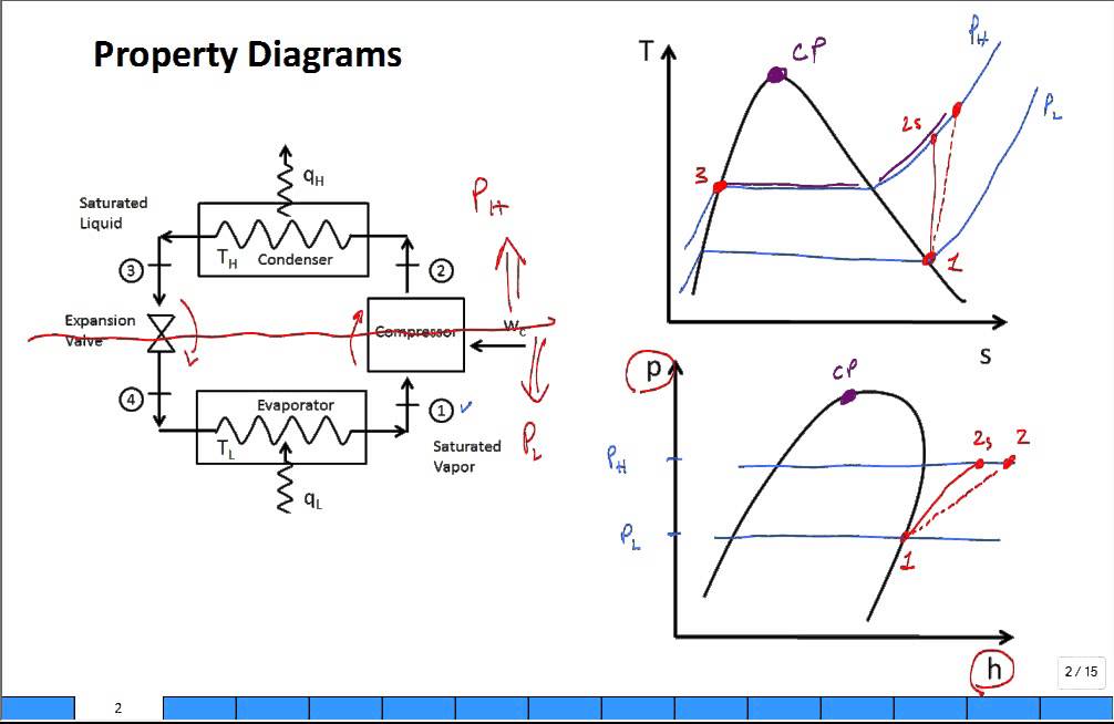
Property Diagrams Ts And Ph For Refrigeration 2 Youtube
Https Resources Saylor Org Wwwresources Archived Site Wp Content Uploads 2013 08 Boleslecturenotesthermodynamicschapter10 Pdf

The cycle as applied in practice however differs considerably from the theoretical cycle.
Actual vapor compression refrigeration cycle t s diagram. Vapor compression refrigeration cycle t s diagram below is a possible cyclepad design of a refrigeration cycle. The t s diagram for a vapor compression refrigeration cycle is shown below. Schematic and t s diagram for the actual vapor compression refrigeration cycle. Vapour compression refrigeration cycle.
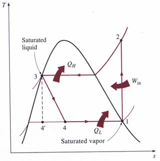
1 in practice the refrigerant enters the compressor at state 1 slightly superheated vapor. 36 25 on t s diagram. The layout shown below is a clickable image. 2 2 2 theoretical vapour compression cycle with dry saturated refrigeration cycle vapour after compression a vapour compression cycle with dry saturated vapour after compression is shown on t s diagrams in figures 2 2 a and b respectively.
Most of the differences between the ideal and the actual cycles are because of the irreversibilities in various components which are. At point 1 let t 1 p 1 and s 1 be the temperature pressure and entropy of the vapour refrigerant. An actual vapor compression refrigeration cycle differs from the ideal one in several ways owing mostly to the irreversibilities that occur in various components mainly due to fluid friction causes pressure drops and heat transfer to or from the surroundings. The theoretical vapour compression cycle.
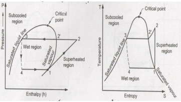
Actual vapour compression refrigeration cycle. T s diagram for actual vapor compression cycle. Actual vapor compression refrigeration cycle fig. The p h and t s diagram for the simple vapor compression refrigeration cycle is shown in the figure for vapour entering the compressor is in dry saturation condition the dry and saturated vapour entering the compressor at point 1 that vapour compresses isentropic ally from point 1 to 2 which increases the pressure from evaporator pressure to condenser.
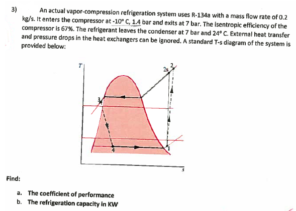
Solved 3 An Actual Vapor Compression Refrigeration Syste Chegg Com
5 Vapour Compression Cycle On Ph And T S Diagrams Lessons Tes Teach
Engineering 41 Laboratory 6

P H Diagram Of The Vapour Compression Refrigeration Cycle Considered In Download Scientific Diagram
Https Resources Saylor Org Wwwresources Archived Site Wp Content Uploads 2013 08 Boleslecturenotesthermodynamicschapter10 Pdf
Energy And Exergy Analysis Of Refrigeration Systems Intechopen
Chapter 11 Refrigeration Cycles Ppt Video Online Download

E2 9 Refrigeration Cycle Experiment Theory
Explain Vapour Compression Refrigeration Cycle On T S And P H Charts Topicwise Paper Solutions For Msbte
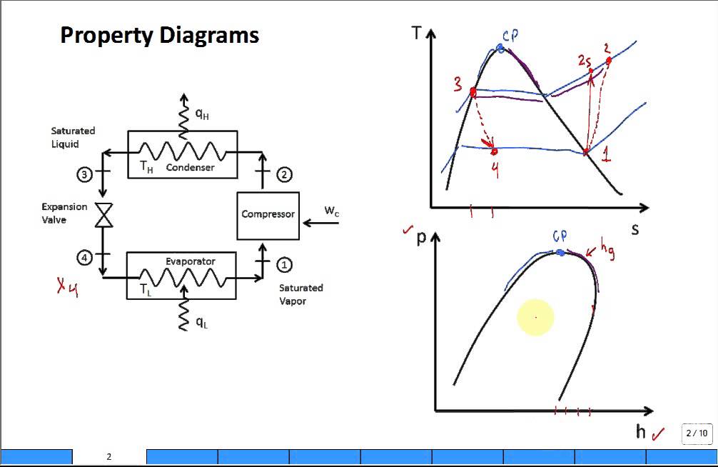
Property Diagrams Ts And Ph For Refrigeration Youtube

Actual Vapour Compression Cycle Actual Vcrs Actual Vapour Cycle Actual Vapor Cycle Youtube

Ch10 Lesson B Page 4 Non Ideal Vapor Compression Refrigeration Cycles
4 T S Diagram For Actual Vapor Compression Refrigeration Cycle 4 Download Scientific Diagram
