Vapor Compression Refrigeration Cycle Ts Diagram

T S Diagram Of The Vapour Compression Refrigeration Cycle Considered In Download Scientific Diagram
Design Of Vapor Compression Refrigeration Cycles
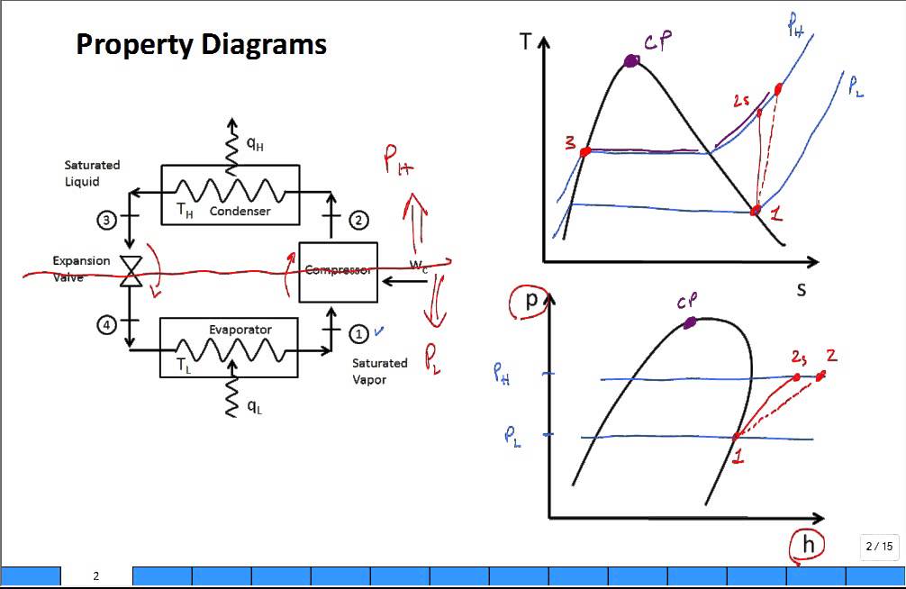
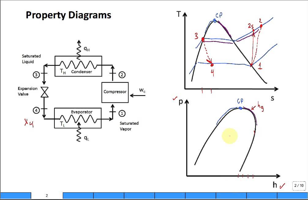
Property Diagrams Ts And Ph For Refrigeration 2 Youtube

6 A B C Schematic And T S Diagram For The Ideal Vapor Compression Download Scientific Diagram

Vapor Compression Refrigeration Wikipedia

Vapor Compression Refrigeration Refrigerator Vapor Compression
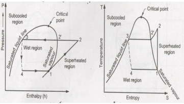
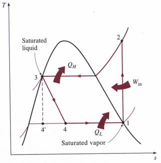
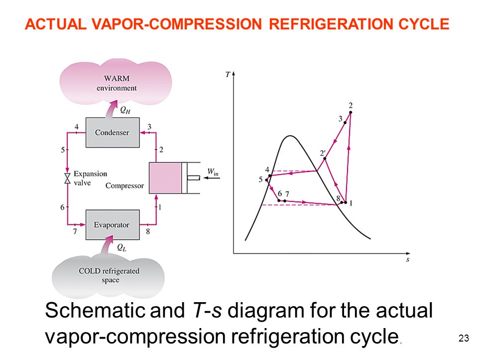
Actual vapour compression refrigeration cycle.
Vapor compression refrigeration cycle ts diagram. In such a case the exit condition of the condenser will be in the subcooled. An actual vapour compression cycle is shown in fig. The layout shown below is a clickable image. Hence it is possible to cool the refrigerant liquid in the condenser to a few degrees lower than the condensing temperature by adding extra area for heat transfer.
Vapor compression refrigeration cycle t s diagram below is a possible cyclepad design of a refrigeration cycle. Actual vapor compression refrigeration cycle fig. In lesson a we presented the problems associated with using the carnot cycle as a practical model for a real vapor compression refrigeration cycle. The cycle as applied in practice however differs considerably from the theoretical cycle.
Some basic refrigeration cycles are discussed here through different diagrams. Most of the differences between the ideal and the actual cycles are because of the irreversibilities in various components which are. Draw t s and p h diagram of sub cooled and super heat vapour compression refrigeration cycle and name. In actual refrigeration cycles the temperature of the heat sink wll be several degrees lower than the condensing temperature to facilitate heat transfer.
The simplest gas refrigeration cycle is the reversed brayton cycle. Sem8 refrigeration and air conditioning. While some people have viewed this method as environmentally harmful and inefficient the cycle is still applicable in the industrial sphere. T s diagram for a vapour compression refrigeration cycle when the refrigerant leaves the evaporator as a saturated vapour b superheated vapour.
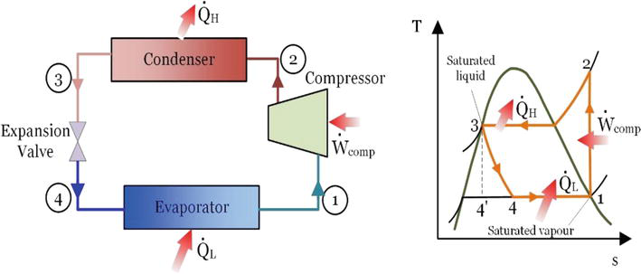
The p h and t s diagram for the simple vapor compression refrigeration cycle is shown in the figure for vapour entering the compressor is in dry saturation condition the dry and saturated vapour entering the compressor at point 1 that vapour compresses isentropic ally from point 1 to 2 which increases the pressure from evaporator pressure to condenser. Most compressors do not work well on two phase mixtures. Ts diagram vapor compression carnot refrigeration cycle. Mumbai university refrigeration and air conditioning 7 1k views.
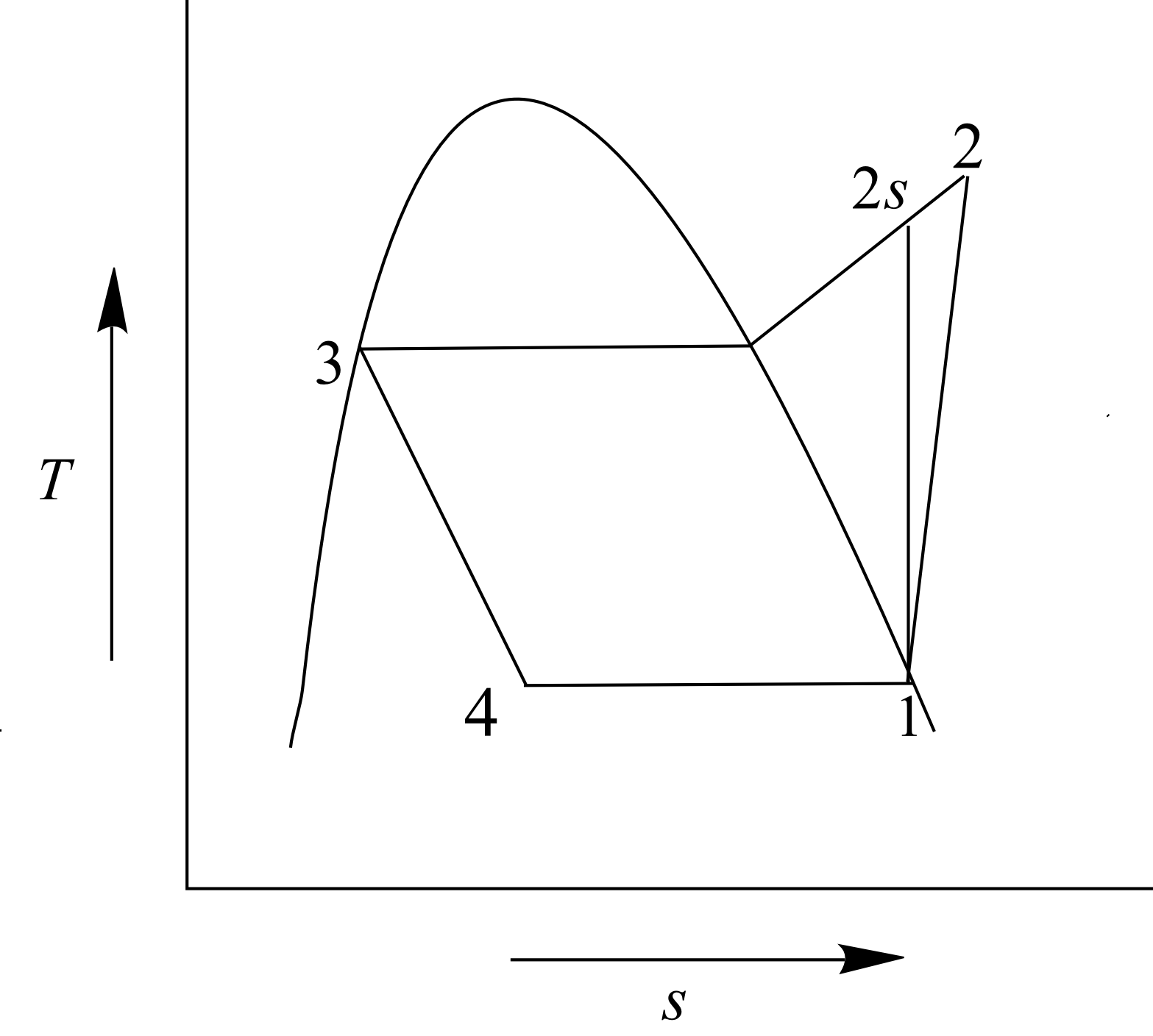
1 in practice the refrigerant enters the compressor at state 1 slightly superheated vapor instead of. The theoretical vapour compression cycle. The t s diagram for a vapor compression refrigeration cycle is shown below. A few of the important points of deviations of this cycle as compared to the ideal.
36 25 on t s diagram. T s diagram for actual vapor compression cycle. Isentropic compression in. 2 2 vapour compression cycle vapour compression cycle is an improved type of air refrigeration cycle in which a suitable.
So refrigeration cycle should be known to understand the refrigeration system. Turbines are not designed to handle vapor liquid mixtures. Refrigeration cycle is the basis of all refrigeration systems. Isentropic compression for state 1.
Gas refrigeration cycle a schematic diagram b t s diagram.

Schmatic And T S Diagram For Ideal Vapor Compression Refrigeration Cycle

A Vapor Compression Refrigeration System Circulates Refrigerant 134a At A Rate Of 6kg Min The Refrigerant Enters The Compressor At 10 O C 1 4 Bar And Exits At 7 Bar The Isentropic Compressor
Explain Vapour Compression Refrigeration Cycle On T S And P H Charts Topicwise Paper Solutions For Msbte
Engineering 41 Laboratory 6
Property Diagrams Ts And Ph For Refrigeration Youtube
Solved Vapor Refrigeration Systems A Vapor Compression Refr Chegg Com

T S Diagram Of Simple Vapour Compression Refrigeration System Download Scientific Diagram
Https Resources Saylor Org Wwwresources Archived Site Wp Content Uploads 2013 08 Boleslecturenotesthermodynamicschapter10 Pdf
Energy And Exergy Analysis Of Refrigeration Systems Intechopen
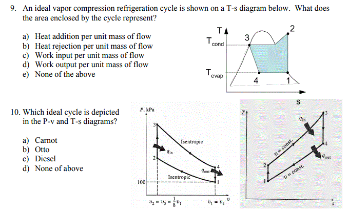
Solved 9 An Ideal Vapor Compression Refrigeration Cycle Chegg Com
5 Vapour Compression Cycle On Ph And T S Diagrams Lessons Tes Teach

Ch10 Lesson B Page 4 Non Ideal Vapor Compression Refrigeration Cycles
Refrigeration
