Vapor Compression Refrigeration Cycle Ts And Ph Diagram
Explain Vapour Compression Refrigeration Cycle On T S And P H Charts Topicwise Paper Solutions For Msbte
Property Diagrams Ts And Ph For Refrigeration 2 Youtube

P H Diagram Of The Vapour Compression Refrigeration Cycle Considered In Download Scientific Diagram
Property Diagrams Ts And Ph For Refrigeration Youtube
Design Of Vapor Compression Refrigeration Cycles

Vapour Compression Refrigeration Cycle On The P H Diagram Download Scientific Diagram

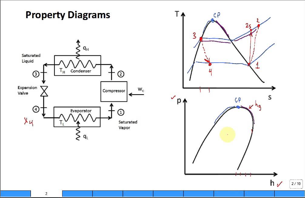
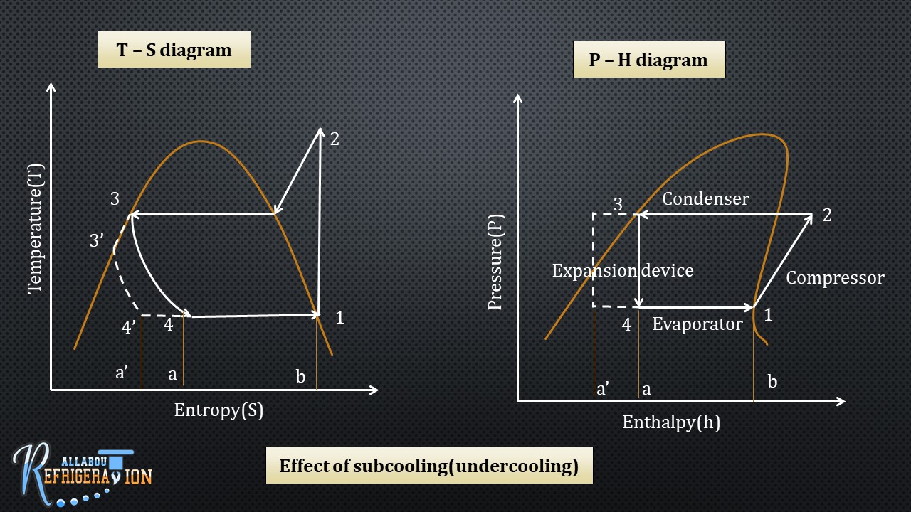
Such a superheating is called useless superheating as it does not increase refrigeration effect.
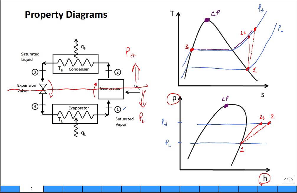
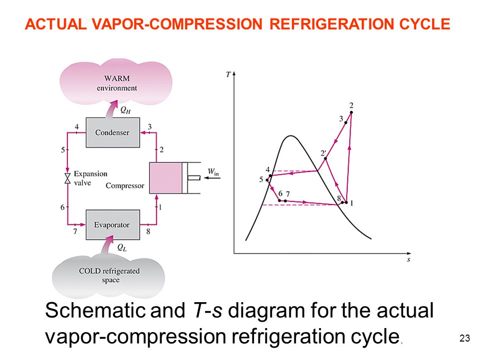
Vapor compression refrigeration cycle ts and ph diagram. 1 2 isentropic compression in compressor. Actual vapour compression refrigeration cycle. 3 4 isenthalpic expansion through expansion valve. The vapor compression refrigeration cycle is nearly 200 years old but it does not seem ready to leave the scene any time soon.
The refrigerant is then. While some people have viewed this method as environmentally harmful and inefficient the cycle is still applicable in the industrial sphere. Low pressure p l refrigerant coming from the evaporator is compressed to a higher pressure p h. The points which are required for engineering calculation are from h 1 to h 6 as shown in the figure 1 6.
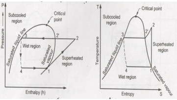
The whole process is explained in brief with the help of this schematic diagram. Fig 1 a and b shows the vcrs cycle without and with subcooling on p h and t s coordinates. Draw t s and p h diagram of sub cooled and super heat vapour compression refrigeration cycle and name. Written 4 1 years ago by ramnath 5 6k.
The t s diagram for a vapor compression refrigeration cycle is shown below. The theoretical vapour. A simple vapour compression cycle is shown by 1 2 3 4 1 on p h chart of fig. Vapor compression refrigeration cycle t s diagram below is a possible cyclepad design of a refrigeration cycle.
Isentropic compression in. H 1 to h. 1 a p h diagram with and without subccoling b t s diagram with and without subcooling. Figure 1 5 refrigeration cycle on the p h diagram take the structure image of this refrigeration cycle from figure 1 5 it becomes the p h diagram for engineering calculation as shown in figure 1 6.
Vapour compression refrigeration cycle p h diagram explain the vapor compression cycle on the t s and p h diagrams for the heated steam at the end of the compression the p h and t s vapor compression cycle for a simple steam compression cooling cycle is shown in the pattern for the steam entering the compressor is in a dry state of saturating dry. The p h and t s diagram for the simple vapor compression refrigeration cycle is shown in the figure for vapour entering the compressor is in dry saturation condition the dry and saturated vapour entering the compressor at point 1 that vapour compresses isentropic ally from point 1 to 2 which increases the pressure from evaporator pressure to condenser pressure at point 2 the saturated vapour. Mumbai university refrigeration and air conditioning 7 1k views. Sem8 refrigeration and air conditioning.
4 1 constant pressure heat absorption. The layout shown below is a clickable image. As the name implies the vapor compression cycle uses a compressor to increase the pressure of the refrigerant or the working fluid.

Property Diagrams Ts And Ph For Refrigeration 2 Youtube

Draw T S And P H Diagram Of Sub Cooled And Super Heat Vapour Compression Refrigeration Cycle And Name The Processes
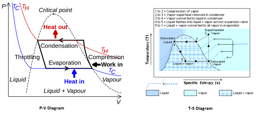
Diagram Vapourpression Refrigeration Cycle T S Diagram Full Version Hd Quality S Diagram Obadiagram Le Saint Germain Fr

P H Diagram Of Vapor Compression Refrigeration Cycle Generally The Download Scientific Diagram
Draw P H And T S Diagram When The Vapours Are Superheated At The End Of Compression And With Under Cooling Of Liquid

Vapor Compression Refrigeration Wikipedia
6 Vapor Compression Cycle

T S Diagram Of The Vapour Compression Refrigeration Cycle Considered In Download Scientific Diagram
5 Vapour Compression Cycle On Ph And T S Diagrams Lessons Tes Teach
Vapor Compression Refrigeration

Diagram R134a Refrigerant T S Diagram Full Version Hd Quality S Diagram Aplotdiagram Looklecco It

Rh 1888 Diagram Refrigeration Cycle Download Diagram

T S And P H Diagram With Sub Cooling And Super Heating
