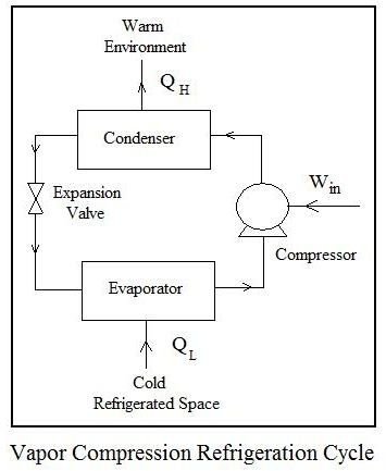
Vapor Compression Refrigeration Cycle Diagram

Vapor Compression Refrigeration Wikipedia

Vapour Compression Refrigeration Cycle On A P H Diagram Download Scientific Diagram

The Vapor Compression Refrigeration Cycle Step By Step

Vapor Compression Refrigeration Wikipedia

Standard Vapour Compression Refrigeration Cycle On P H Diagram Download Scientific Diagram
Design Of Vapor Compression Refrigeration Cycles
In this cycle the refrigerant is sealed condition in an airtight mechanism is compressed in a compressor which permits the transfer of heat energy.
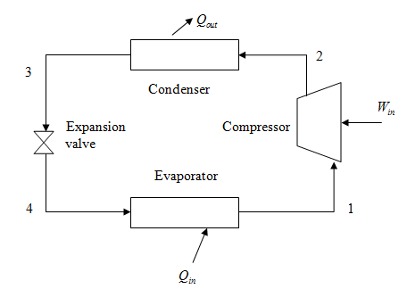
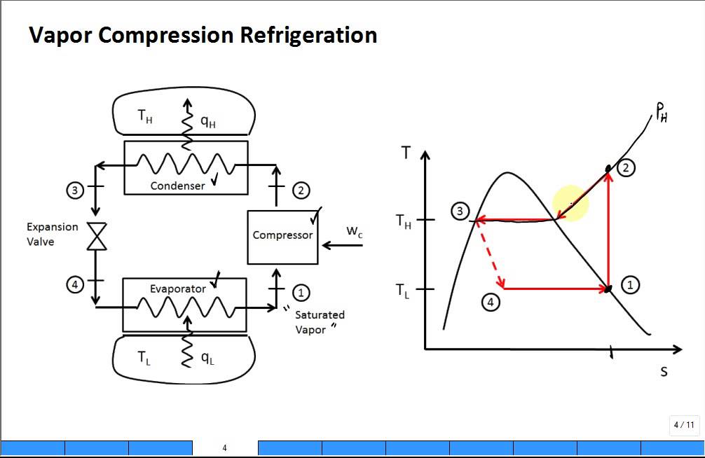
Vapor compression refrigeration cycle diagram. A low pressure low temperature liquid is converted to vapor in the evaporator thus absorbing heat from the refrigerated space and keeping that space cool. The vapor compression refrigeration cycle. 1 in practice the refrigerant enters the compressor at state 1 slightly superheated vapor instead of. While some people have viewed this method as environmentally harmful and inefficient the cycle is still applicable in the industrial sphere.
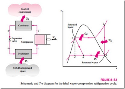
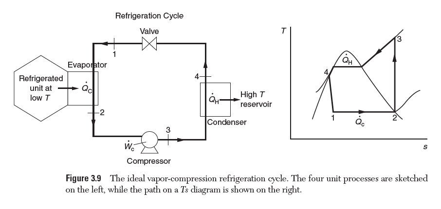
The vapor compression refrigeration cycle is nearly 200 years old but it does not seem ready to leave the scene any time soon. Vapor compression refrigeration cycle t s diagram below is a possible cyclepad design of a refrigeration cycle. The cycle as applied in practice however differs considerably from the theoretical cycle. A compressor condenser expansion valve and evaporator.
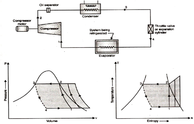
Actual vapor compression refrigeration cycle fig. Vapour compression cycle generally known as vcc is a refrigeration cycle. Vapour compression refrigeration cycle. At point 1 let t 1 p 1 and s 1 be the temperature pressure and entropy of the vapour refrigerant.
Vapor compression cycle thermodynamic cycle of heat pumps. The layout shown below is a clickable image. A few of the important points of deviations of this cycle as compared to the ideal. An actual vapour compression cycle is shown in fig.
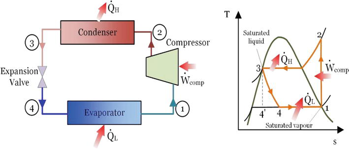
Actual vapour compression refrigeration cycle. 36 25 on t s diagram. Vapour compression refrigeration cycle p h diagram explain the vapor compression cycle on the t s and p h diagrams for the heated steam at the end of the compression the p h and t s vapor compression cycle for a simple steam compression cooling cycle is shown in the pattern for the steam entering the compressor is in a dry state of saturating dry. The diagram at the left shows the components of a vapor compression refrigeration cycle.
T s diagram for actual vapor compression cycle. The refrigerant absorbs heat from one place and releases it to another place. Most of the differences between the ideal and the actual cycles are because of the irreversibilities in various components which are. The t s diagram for a vapor compression refrigeration cycle is shown below.
The theoretical vapour compression cycle.
Vapor Compression Refrigeration

Vapor Compression Refrigeration Systems Refrigerator Troubleshooting Diagram

Typical Vapor Compression Refrigeration Vcr Cycle Enggcyclopedia

P H Diagram Of The Vapour Compression Refrigeration Cycle Considered In Download Scientific Diagram
Modify The Vapor Compression Refrigeration System Chegg Com
Intro Refrigeration Cycle Vapor Compression Youtube
Power And Refriger A Tion Cycles The Ideal Vapor Compression Refrigeration Cycle Hydraulics And Pneumatics
Refrigeration Process Refrigerant Vapor Compression Cycle Bright Hub Engineering
Vapour Compression Refrigeration Cycle Engineering Tutorials
Energy And Exergy Analysis Of Refrigeration Systems Intechopen

Schmatic And T S Diagram For Actual Vapor Compression Refrigeration Cycle

Vapour Compression Refrigeration Cycle It S Schematic And T S P H Diagram Youtube

Vapor Compression Cycle