Simple Vapor Compression Refrigeration Cycle

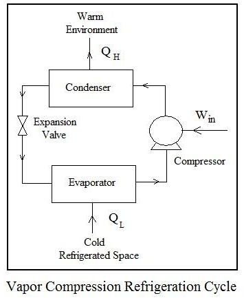
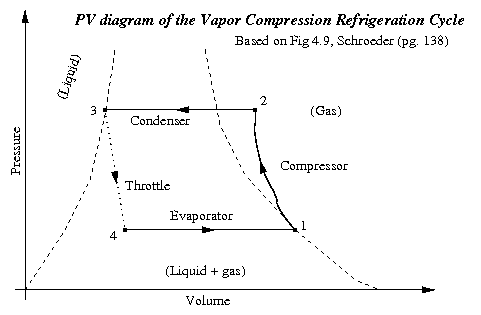
The figure depicts a typical single stage vapor compression system.
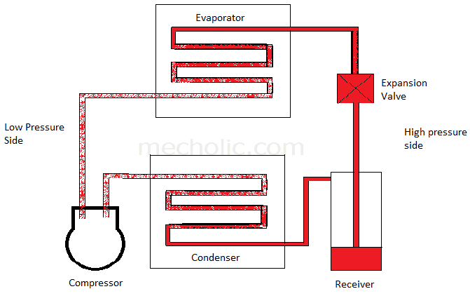
Simple vapor compression refrigeration cycle. A compressor condenser expansion valve and evaporator. It is a compression process whose aim is to raise the refrigerant pressure as it flows from an evaporator. In this case the expansion valve is highly irreversible and is therefore causing a great deal of lost work and a loss of efficiency. It is also used in domestic and commercial refrigerators large scale warehouses for chilled or frozen storage of foods and meats refrigerated trucks and railroad cars and a host of other commercial and industrial services.
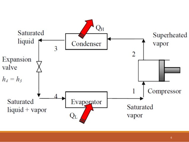
2 3 constant pressure cooling heat rejection. 2b absorber and generator vapor absorption cycle. Compressor condenser expansion valve throttle valve and evaporator. Vapor compression cycle thermodynamic cycle of heat pumps.
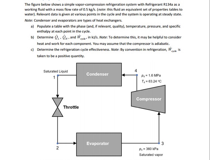
The vapor compression refrigeration cycle. 3 4 isenthalpic expansion through expansion valve. Refrigeration cycles 6 5 simple vapor compression refrigeration system. The vapor compression refrigeration cycle involves four components.
The refrigeration cycle animation in video above describes this process. Vapour compression refrigeration or vapor compression refrigeration system in which the refrigerant undergoes phase changes is one of the many refrigeration cycles and is the most widely used method for air conditioning of buildings and automobiles. A simple vapour compression cycle is shown by 1 2 3 4 1 on p h chart of fig. The vapor compression uses a circulating liquid refrigerant as the medium usually r134a which absorbs and removes heat from the space to be cooled and subsequently rejects that heat elsewhere.
The typical vapor compression system consist of four components. The vapor is raised to a pressure such that its corresponding boiling condensing point temperature becomes higher than that of a cooling medium like water or air available at atmospheric temperature. Mechanism of simple vcrs assumptions for ideal vapor compression cycle are. Hence the system is called a vapor compression cycle.
1 2 isentropic compression in compressor. Actual vapour compression refrigeration cycle. Irreversibility within the evaporator condenser and compressor are ignored no frictional pressure drops refrigerant flows at constant pressure through the two heat exchangers evaporator and condenser heat losses to the surroundings are ignored compression process is isentropic main components are. The p h and t s diagram for the simple vapor compression refrigeration cycle is shown in the figure for vapour entering the compressor is in dry saturation condition the dry and saturated vapour entering the compressor at point 1 that vapour compresses isentropic ally from point 1 to 2 which increases the pressure from evaporator pressure to condenser.
The diagram at the left shows the components of a vapor compression refrigeration cycle. Simple vapour compression cycle on p h chart. Compressor condenser expansion devices evaporator 5. A low pressure low temperature liquid is converted to vapor in the evaporator thus absorbing heat from the refrigerated space and keeping that space cool.


