Ideal Vapor Compression Refrigeration Cycle

Schematic Diagram For The Ideal Vapor Compression Refrigeration Cycle 8 Download Scientific Diagram
Power And Refriger A Tion Cycles The Ideal Vapor Compression Refrigeration Cycle Hydraulics And Pneumatics

The Ideal Vapour Compression Refrigeration Cycle Download Scientific Diagram
Solved Refrigerant 134a Is The Working Fluid In An Ideal Chegg Com

6 A B C Schematic And T S Diagram For The Ideal Vapor Compression Download Scientific Diagram
Solved 2 An Ideal Vapor Compression Refrigeration Cycle Chegg Com

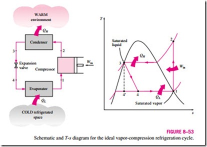
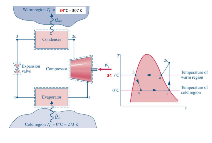
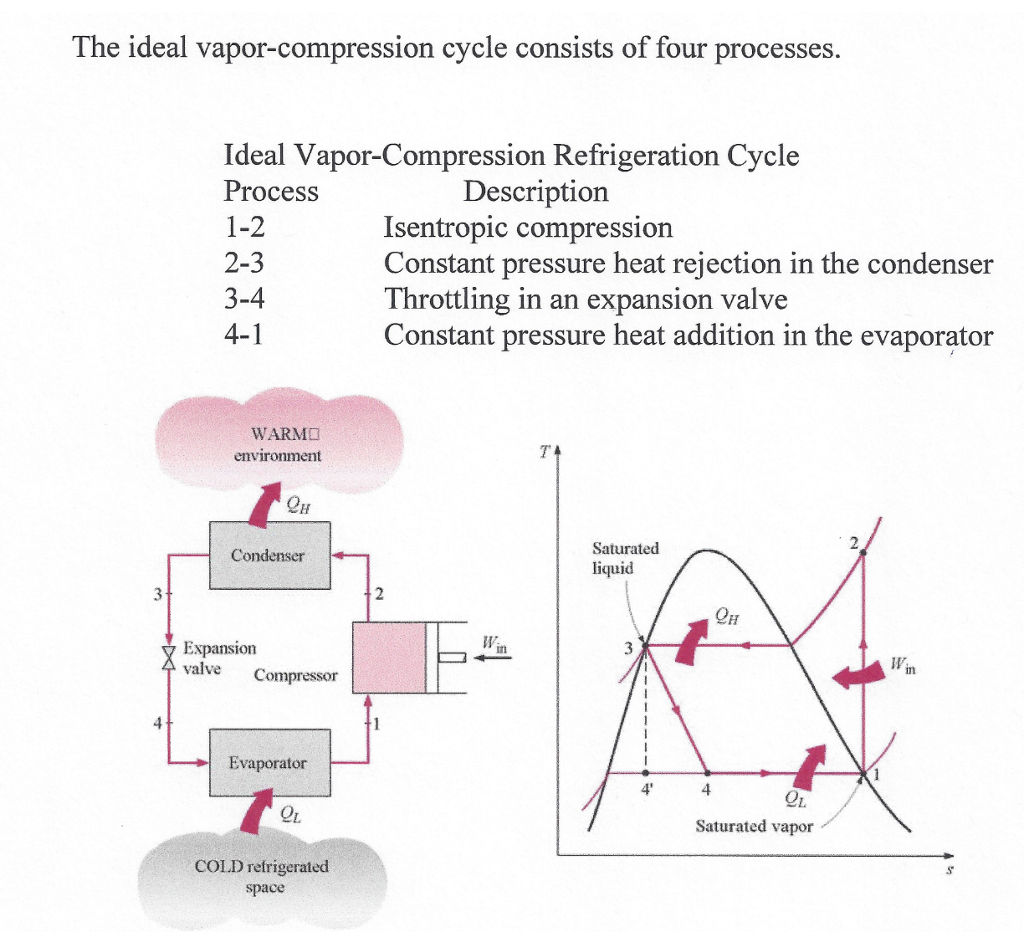
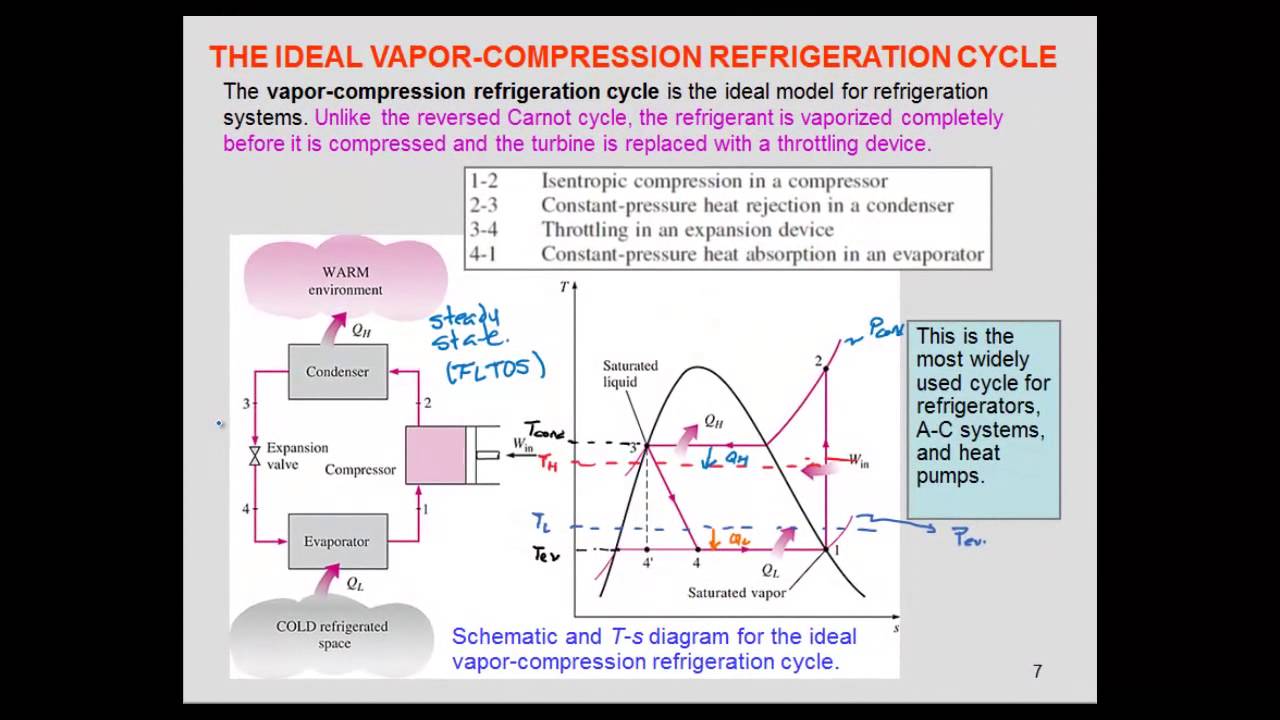
Compressor condenser expansion valve throttle valve and evaporator.
Ideal vapor compression refrigeration cycle. It is a compression process whose aim is to raise the refrigerant pressure as it flows from an evaporator. Unlike other ideal cycles carnot cycle the ideal vapor compression refrigeration cycle is not an internally reversible cycle since it involves an irreversible throttling process. Pressure drop across the evaporator is caused by fluid friction. The cycle consists of.
In an ideal vapour compression refrigeration cycle the compression process is isentropic. In an ideal vapor compression refrigeration cycle the refrigerant enters the. Heat exchanges between the fluid and the chamber walls alter this compression process to deviate from the idealized isentropic process. It is also used in domestic and commercial refrigerators large scale warehouses for chilled or frozen storage of foods and meats.
The vapor compression refrigeration cycle involves four components. Isothermal processes are replaced by constant pressure processes. Vapour compression refrigeration or vapor compression refrigeration system vcrs in which the refrigerant undergoes phase changes is one of the many refrigeration cycles and is the most widely used method for air conditioning of buildings and automobiles. A parameter called isentropic efficiency can be used to calculate this deviation as expressed in eq.
Ch 10 lesson b page 2 the ideal vapor compression refrigeration cycle. Mechanical and fluid friction in the compressor cause the entropy of the working fluid to increase. Non ideal vapor compression refrigeration cycles. This process is maintained in the cycle to make it a more realistic model for the actual vapor compression refrigeration cycle.
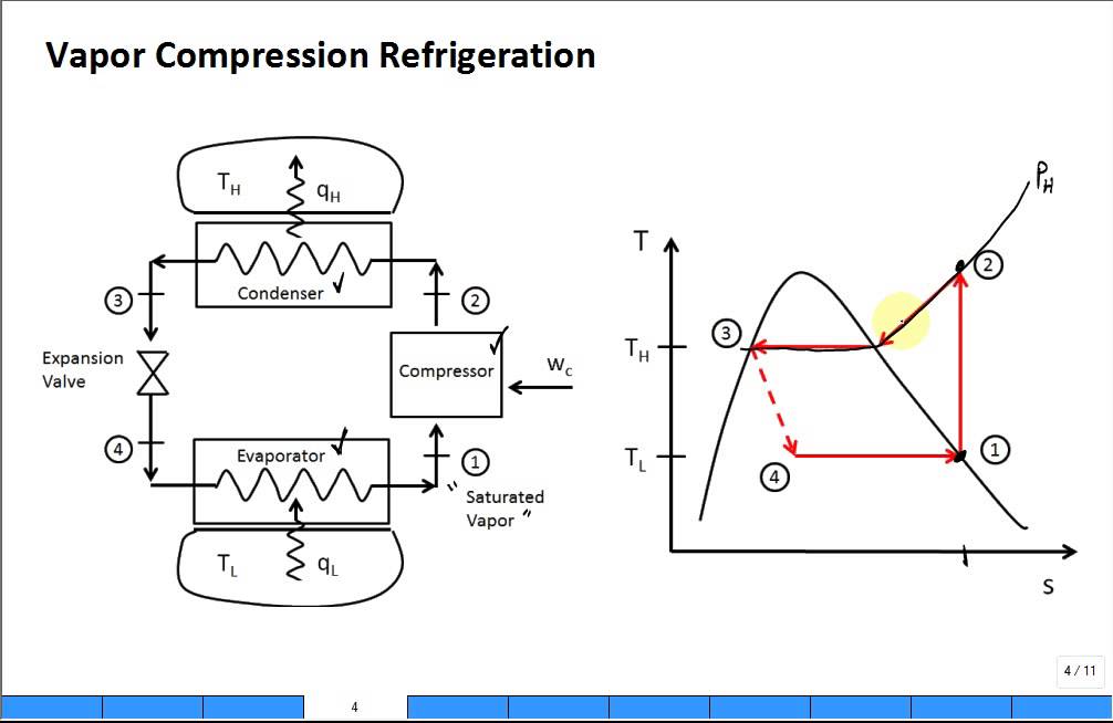
The vapor compression uses a circulating liquid refrigerant as the medium usually r134a which absorbs and removes heat from the space to be cooled and subsequently rejects that heat elsewhere the figure depicts a typical single stage vapor compression system the typical vapor compression system consist of four components. Evaporator compressor condenser and expansion or throttle valve. Deviations from the ideal vapor compression refrigeration cycle. It s even ok if the compressor feed is slightly superheated.
Vapor compression cycle thermodynamic cycle of heat pumps. Replacing the turbine by a throttle valve. P 2 p 1. The most widely used refrigeration cycle is the vapor compression refrigeration cycle.
The easiest way to improve the quality of the feed to the compressor is to make sure that the evaporator completely vaporizes the working fluid.
Https Resources Saylor Org Wwwresources Archived Site Wp Content Uploads 2013 08 Boleslecturenotesthermodynamicschapter10 Pdf
Https Resources Saylor Org Wwwresources Archived Site Wp Content Uploads 2013 08 Boleslecturenotesthermodynamicschapter10 Pdf
Schmatic And T S Diagram For Ideal Vapor Compression Refrigeration Cycle
Solved An Ideal Vapor Compression Refrigeration Cycle Use Chegg Com

E2 9 Refrigeration Cycle Experiment Theory
Design Of Vapor Compression Refrigeration Cycles

Vapor Compression Refrigeration Wikipedia
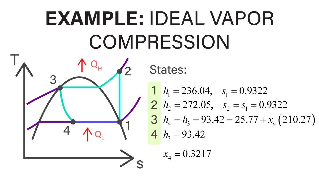
Mechanical Engineering Thermodynamics Lec 23 Pt 4 Of 4 Example Ideal Vapor Compression Youtube

Refrigeration Cycles Chapter 11 Ert 206 4 Thermodynamics Ppt Video Online Download
Intro Refrigeration Cycle Vapor Compression Youtube

Ideal Vapour Compression Refrigeration Cycle In P H Diagram Download Scientific Diagram
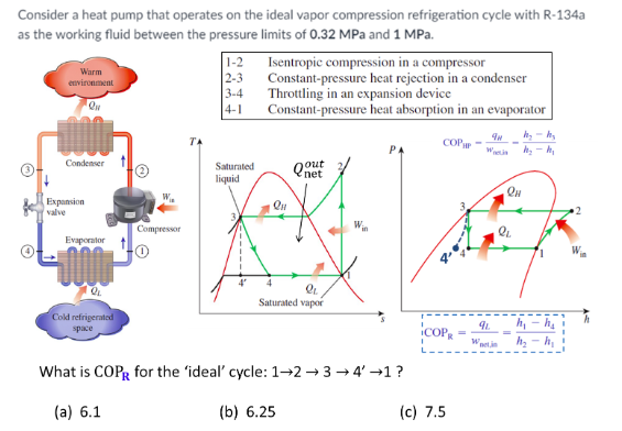
Solved Consider A Heat Pump That Operates On The Ideal Va Chegg Com
Refrigeration Ideal Vapor Compression Cycle Youtube
