Ideal Vapor Compression Refrigeration Cycle Ts Diagram

B T S Diagram Of Ideal Vapor Compression Refrigeration And Download Scientific Diagram

6 A B C Schematic And T S Diagram For The Ideal Vapor Compression Download Scientific Diagram

T S Diagram Of The Vapour Compression Refrigeration Cycle Considered In Download Scientific Diagram

Schmatic And T S Diagram For Ideal Vapor Compression Refrigeration Cycle

6 A B C Schematic And T S Diagram For The Ideal Vapor Compression Download Scientific Diagram
Engineering 41 Laboratory 6
Slide 3 of 24.
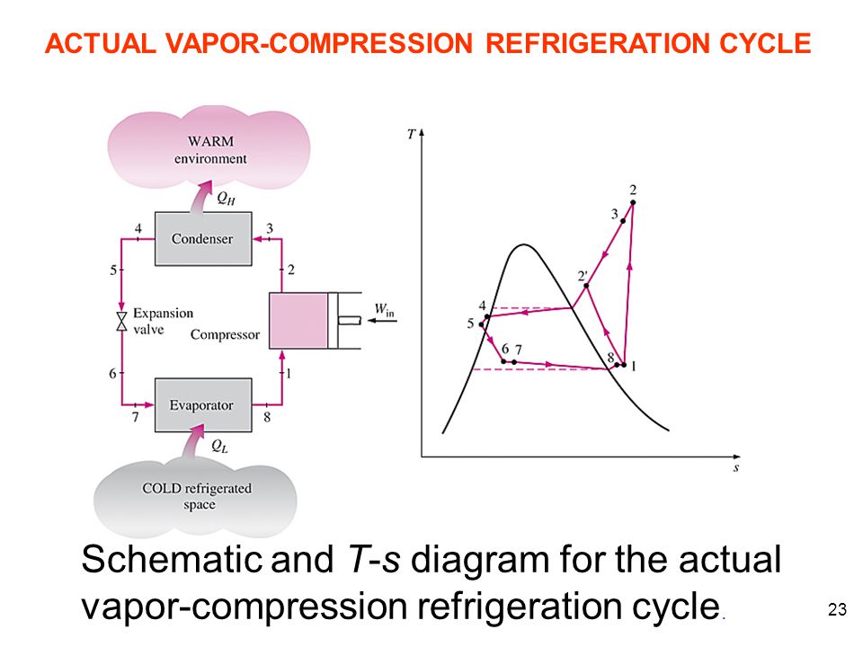
Ideal vapor compression refrigeration cycle ts diagram. Practical vapour compression refrigeration cycle a schematic diagram b t s diagram. The cop of the refrigerator is given by in the ideal. A few of the important points of deviations of this cycle as compared to the ideal. The cycle as applied in practice however differs considerably from the theoretical cycle.
And q l h 1 h 4. H 3 h 4. Actual vapour compression refrigeration cycle. Actual vapor compression refrigeration cycle fig.
It s even ok if the compressor feed is slightly superheated. The design is to be based upon the ideal vapor compression refrigeration cycle with four components. A cooler where we reject the heat a throttle a heater where we absorb the. The easiest way to improve the quality of the feed to the compressor is to make sure that the evaporator completely vaporizes the working fluid.
1 in practice the refrigerant enters the compressor at state 1 slightly superheated vapor instead of. We want to design a vapor compression refrigeration cycle to absorb heat from a cool environment and reject it to a warm environment. Most of the differences between the ideal and the actual cycles are because of the irreversibilities in various components which are. While some people have viewed this method as environmentally harmful and inefficient the cycle is still applicable in the industrial sphere.
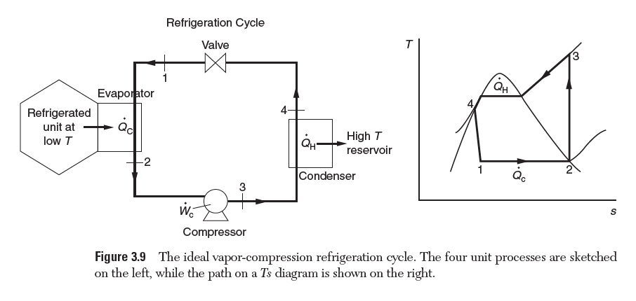
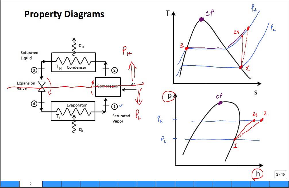
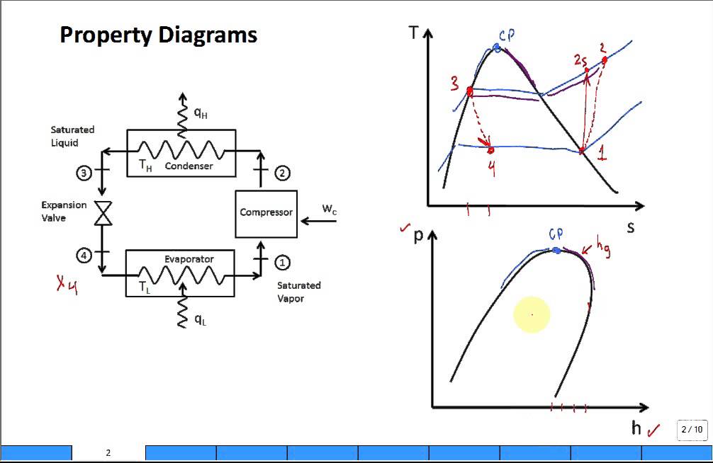
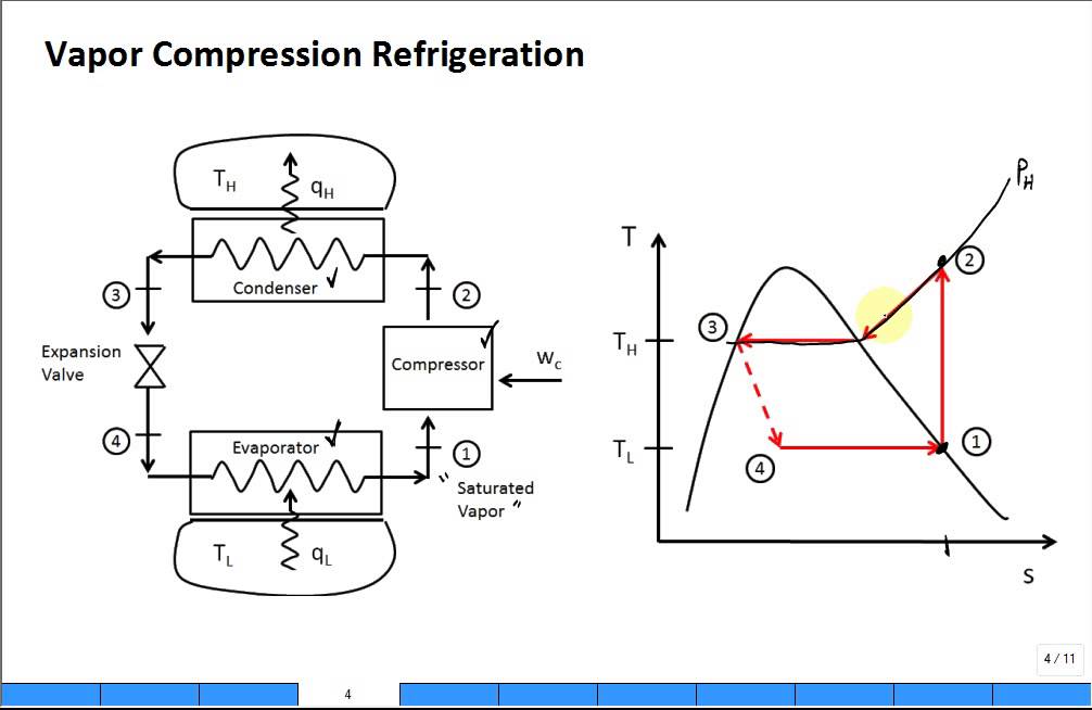
36 25 on t s diagram. The vapor compression refrigeration cycle is nearly 200 years old but it does not seem ready to leave the scene any time soon. Ch 10 lesson b page 2 the ideal vapor compression refrigeration cycle. Ideal vapor compression refrigeration cycle process description 1 2 isentropic compression 2 3 constant pressure heat rejection in the condenser 3 4 throttling in an expansion valve 4 1 constant pressure heat addition in the evaporator.
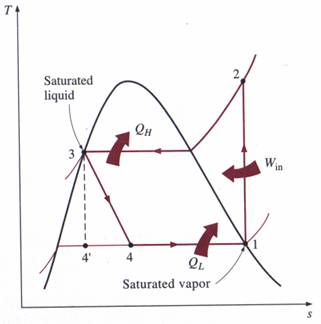
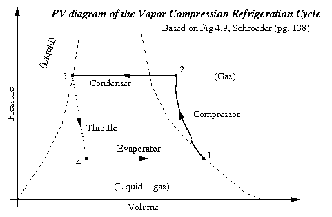
The p h and t s diagram for the simple vapor compression refrigeration cycle is shown in the figure for vapour entering the compressor is in dry saturation condition the dry and saturated vapour entering the compressor at point 1 that vapour compresses isentropic ally from point 1 to 2 which increases the pressure from evaporator pressure to condenser. Q h h 2 h 3. An actual vapour compression cycle is shown in fig. The theoretical vapour compression cycle.
Chapter 10 5 the p h diagram is another convenient diagram often used to illustrate the refrigeration cycle.
Vapor Compression Refrigeration
Solved 9 An Ideal Vapor Compression Refrigeration Cycle Chegg Com
Property Diagrams Ts And Ph For Refrigeration 2 Youtube
Https Resources Saylor Org Wwwresources Archived Site Wp Content Uploads 2013 08 Boleslecturenotesthermodynamicschapter10 Pdf

Vapor Compression Refrigeration Wikipedia

Ch10 Lesson B Page 3 Cop Ideal Vapor Compression Refrigeration Cycles
Explain Vapour Compression Refrigeration Cycle On T S And P H Charts Topicwise Paper Solutions For Msbte
Property Diagrams Ts And Ph For Refrigeration Youtube
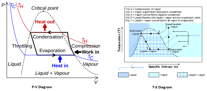
Diagram Vapourpression Refrigeration Cycle T S Diagram Full Version Hd Quality S Diagram Obadiagram Le Saint Germain Fr
5 Vapour Compression Cycle On Ph And T S Diagrams Lessons Tes Teach
Intro Refrigeration Cycle Vapor Compression Youtube

P H Diagram Of The Vapour Compression Refrigeration Cycle Considered In Download Scientific Diagram

Refrigeration Cycles Chapter 11 Ert 206 4 Thermodynamics Ppt Video Online Download