Actual Vapor Compression Refrigeration Cycle P H Diagram

P H Diagram Of Vapor Compression Refrigeration Cycle Generally The Download Scientific Diagram

Vapour Compression Refrigeration Cycle On A P H Diagram Download Scientific Diagram

P H Diagrams Of A Typical Refrigeration Cycle And B Subcooled And Download Scientific Diagram

Actual Vapour Compression Cycle And The Effect Of Suction And Discharge Pressure

Actual Vapour Compression Cycle Actual Vcrs Actual Vapour Cycle Actual Vapor Cycle Youtube
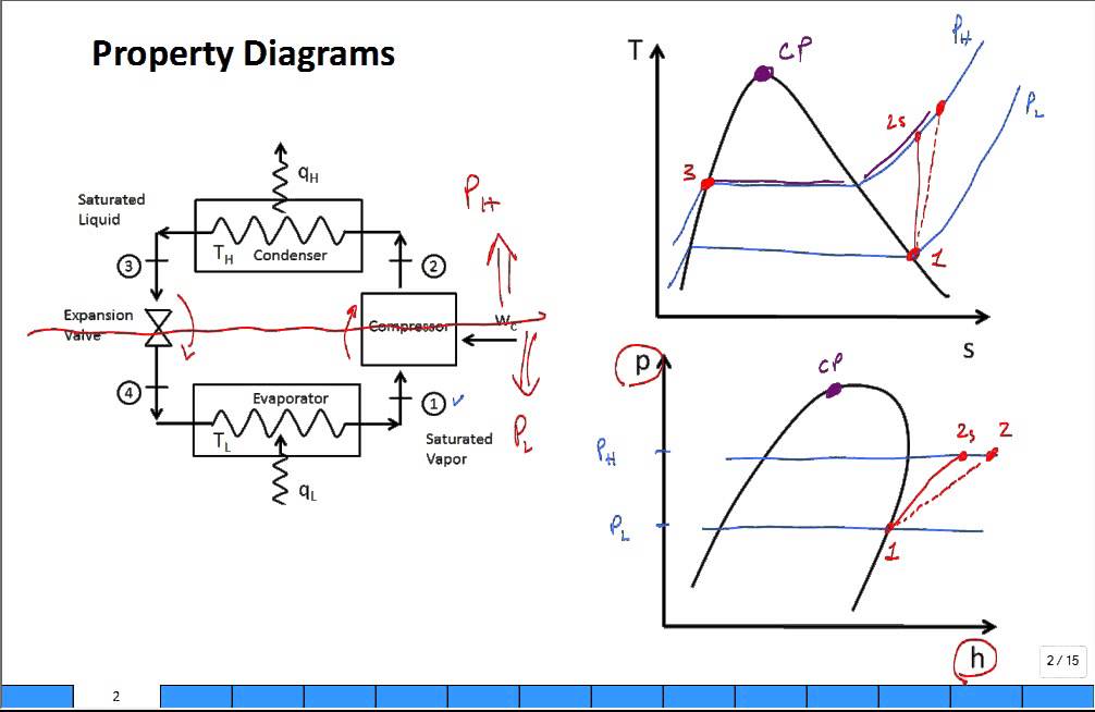
Property Diagrams Ts And Ph For Refrigeration 2 Youtube

This case is also to evaluate various cycles such as with penalties economizing for a single stage compression refrigeration systems which are based on the same ct et and tr as the following.
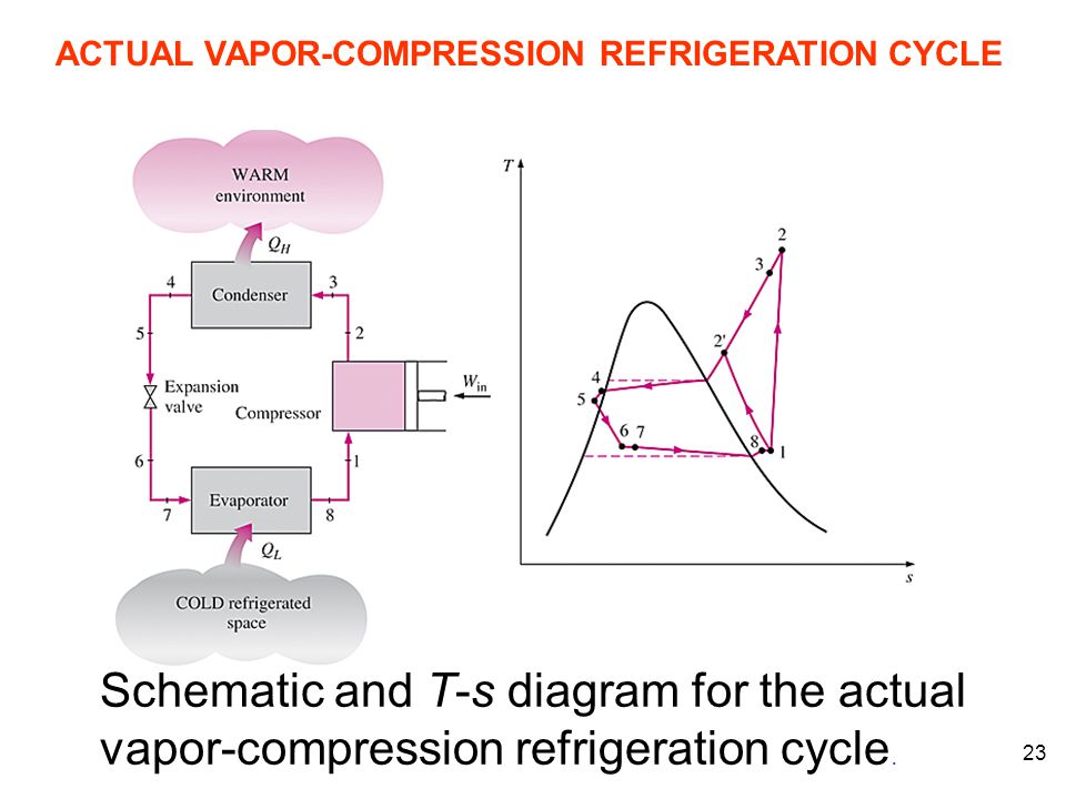
Actual vapor compression refrigeration cycle p h diagram. An actual vapor compression refrigeration cycle differs from the ideal one in several ways owing mostly to the irreversibilities that occur in various. T s diagram for actual vapour compression cycle. Ejector and conventional compression system. My question is.
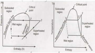
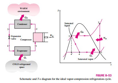
The ideal vapor compression refrigeration cycle involves an irreversible. Por compressão de vapor. The performance of refrigeration plant is expressed as co efficient of performance cop which is defined as the ratio of refrigerating effect produced to the work of compression. The actual vapour compression cycle is different from the theoretical vapour compression cycle in many ways.
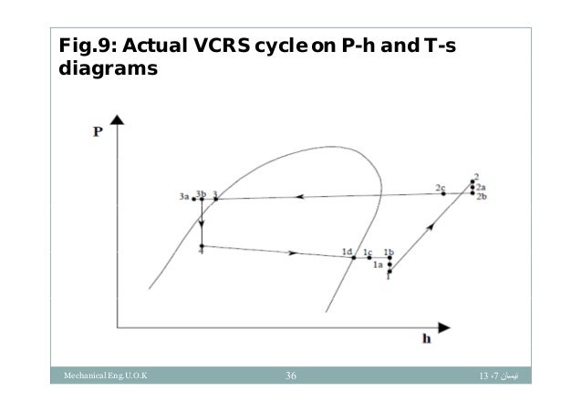
The refrigerant flow diagram corresponding to the p h diagram. Actual vapour compression cycle fig. T s diagram for actual vapor compression cycle. Most of the differences between the ideal and the actual cycles are because of the irreversibilities in various components which are.
The vapor compression refrigeration cycle is nearly 200 years old but it does not seem ready to leave the scene any time soon. 4 1 actual vapor compression refrigeration cycle on p h diagram. The main deviations between the theoretical and actual cycle are. 1 in practice the refrigerant enters the compressor at state 1 slightly superheated vapor.
Thermodynamic analysis of the refrigeration cycle using the p h diagram. Theoretical vapour compression cycle with dry saturated vapour after compression compression process the vapour refrigerant at low pressure p 1 and temperaturet 1 is compressed isentropically to dry saturated vapour as shown by the vertical line 1 2 on the t s. Actual vapor compression refrigeration cycle fig. The p h diagram of an ideal vapor compression refrigeration cycle.
Vapour compression refrigeration cycle p h diagram explain the vapor compression cycle on the t s and p h diagrams for the heated steam at the end of the compression the p h and t s vapor compression cycle for a simple steam compression cooling cycle is shown in the pattern for the steam entering the compressor is in a dry state of saturating dry. Software for plotting a comparison of actual cycle p h diagram of refrigeration. 4 3 performance of refrigeration system. Vapour compression refrigeration cycle it s schematic and t s p h diagram.
While some people have viewed this method as environmentally harmful and inefficient the cycle is still applicable in the industrial sphere. Actual vapor compression cycle thermal science.
Explain Vapour Compression Refrigeration Cycle On T S And P H Charts Topicwise Paper Solutions For Msbte
Vapour Compression Refrigeration System
P H Diagram Of The Vapour Compression Refrigeration Cycle Considered In Download Scientific Diagram
Https Resources Saylor Org Wwwresources Archived Site Wp Content Uploads 2013 08 Boleslecturenotesthermodynamicschapter10 Pdf

Refrigeration
Https Projects Ncsu Edu Project Foodengineer 231 Labs Refrigeration Refrigeration Lab Ppt Pdf

Ws 4088 Of Refrigeration Cycle Ph Diagram Analysis Refrigerant Flow Diagram Free Diagram
5 Vapour Compression Cycle On Ph And T S Diagrams Lessons Tes Teach
Power And Refriger A Tion Cycles The Ideal Vapor Compression Refrigeration Cycle Hydraulics And Pneumatics
Jsrae Japanese Society For Refrigerating And Airconditioning Engineers

Efficiency Measuring Refrigeration
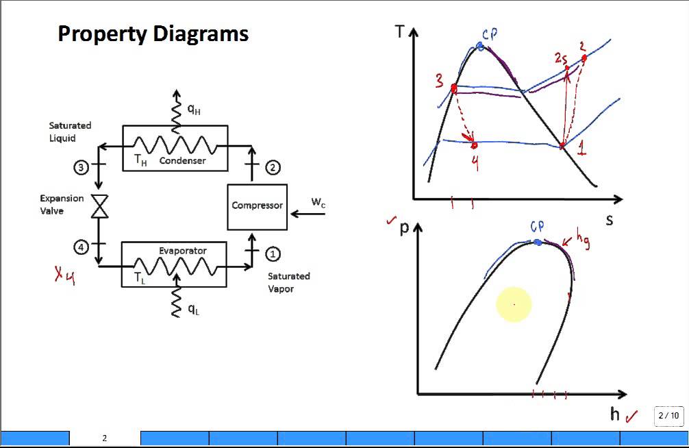
Property Diagrams Ts And Ph For Refrigeration Youtube

Thermoeconomic Optimization Of Subcooled And Superheated Vapor Compression Refrigeration Cycle Sciencedirect
