Actual Simple Vapor Compression Refrigeration Cycle
Https Resources Saylor Org Wwwresources Archived Site Wp Content Uploads 2013 08 Boleslecturenotesthermodynamicschapter10 Pdf
Https Resources Saylor Org Wwwresources Archived Site Wp Content Uploads 2013 08 Boleslecturenotesthermodynamicschapter10 Pdf

Actual Vapour Compression Cycle And The Effect Of Suction And Discharge Pressure

Chapter 11 Refrigeration Cycles Ppt Video Online Download

Actual Vapor Compression Cycle Youtube

1 Simple Vapour Compression Refrigeration System Download Scientific Diagram
2 2 vapour compression cycle 2 2 1 simple vapour compression refrigeration cycle 2 2 2 theoretical vapour compression cycle with saturated vapour after compression 2 2 2 conditions for highest cop 2 2 3 carnot refrigeration cycle 2 2 4 temperature limitations 2 2 5 difference between refrigeration and heat pump cycles.
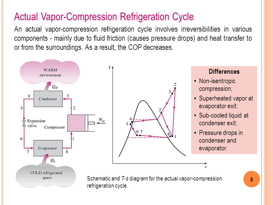
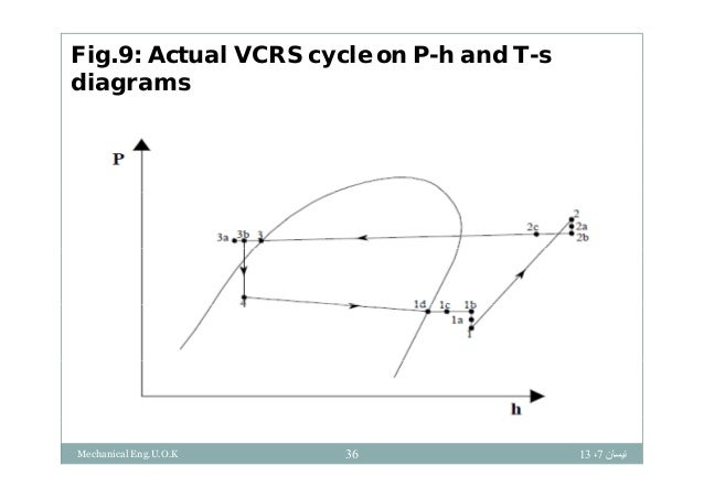
Actual simple vapor compression refrigeration cycle. Vapor compression cycle thermodynamic cycle of heat pumps. A few of the important points of deviations of this cycle as compared to the ideal. Actual vapor compression refrigeration cycle fig. 36 25 on t s diagram.
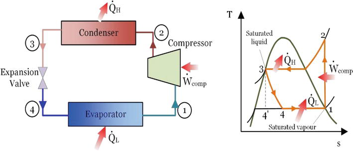
Actual vapour compression refrigeration cycle. The vapor compression uses a circulating liquid refrigerant as the medium usually r134a which absorbs and removes heat from the space to be cooled and subsequently rejects that heat elsewhere the figure depicts a typical single stage vapor compression system the typical vapor compression system consist of four components. The above figure shows the objectives of refrigerators and heat pumps. The purpose of a refrigerator is the removal of heat called the cooling load from a low temperature medium.
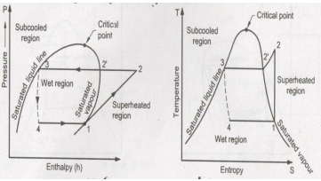
The vapor usually leaves the evaporator is superheated to prevent droplet of liquid within the compressor. 4 1 actual vapor compression refrigeration cycle on p h diagram. When a simple v c refrigeration cycle is used to make the refrigerated space very cood the difference between the operating pressures in the evaporator and condenser become very large. The theoretical vapour compression cycle.
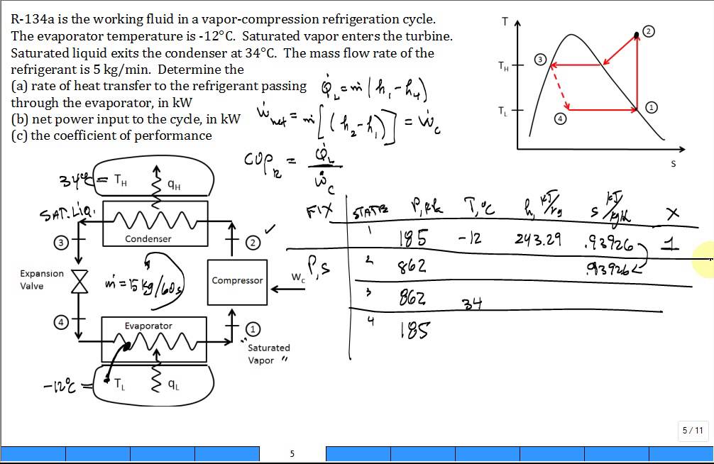
Most of the differences between the ideal and the actual cycles are because of the irreversibilities in various components which are. 1 in practice the refrigerant enters the compressor at state 1 slightly superheated vapor. Actual vapour compression cycle. The performance of refrigeration plant is expressed as co efficient of performance cop which is defined as the ratio of refrigerating effect produced to the work of compression.
Vapour compression refrigeration cycle it s schematic and t s p h diagram. The actual vapour compression cycle differs from the standard cycle due to the following reasons. T s diagram for actual vapor compression cycle. The vapor compression refrigeration cycle is nearly 200 years old but it does not seem ready to leave the scene any time soon.
Refrigeration cycles the vapor compression refrigeration cycle is a common method for transferring heat from a low temperature to a high temperature. 4 3 performance of refrigeration system. An actual vapour compression cycle is shown in fig. The cycle as applied in practice however differs considerably from the theoretical cycle.
While some people have viewed this method as environmentally harmful and inefficient the cycle is still applicable in the industrial sphere. Simple vapour absorption system actual vapour absorption.

T S Diagram Of The Vapour Compression Refrigeration Cycle Considered In Download Scientific Diagram
Calc Vapor Compression Refrigeration Cycle R134a Youtube
Explain Vapour Compression Refrigeration Cycle On T S And P H Charts Topicwise Paper Solutions For Msbte

Vapour Compression Refrigeration Cycle On A P H Diagram Download Scientific Diagram

Ch10 Lesson B Page 4 Non Ideal Vapor Compression Refrigeration Cycles

Actual Vapour Compression Cycle Actual Vcrs Actual Vapour Cycle Actual Vapor Cycle Youtube
Chapter 11 Refrigeration Cycles Ppt Video Online Download
Energy And Exergy Analysis Of Refrigeration Systems Intechopen
Design Of Vapor Compression Refrigeration Cycles

Standard Vapour Compression Refrigeration Cycle On P H Diagram Download Scientific Diagram

Thermodynamics Ii Chapter 5 Refrigeration Ppt Video Online Download

E2 9 Refrigeration Cycle Experiment Theory
Vapour Compression Refrigeration System
